Friday, September 16, 2016

comparison of different raid types


Features
Minimum # Drives
2
2
3
3
4
Data Protection
No Protection
Single-drive failure
Read Performance
High
High
High
High
High
Write Performance
High
Medium
Medium
Low
Low
Read Performance (degraded)
N/A
Medium
High
Low
Low
Write Performance (degraded)
N/A
High
High
Low
Low
Capacity Utilization
100%
50%
50%
67% - 94%
50% - 88%
Typical Applications
High End Workstations, data logging, real-time rendering, very transitory data
Operating System, transaction databases
Operating system, transaction databases
Data warehousing, web serving, archiving
Features
Minimum # Drives
4
4
6
8
Data Protection
Two-drive failure
Up to one disk failure in each sub-array
Up to two disk failure in each sub-array
Read Performance
High
High
High
High
Write Performance
Low
Medium
Medium
Medium
Read Performance (degraded)
Low
High
Medium
Medium
Write Performance (degraded)
Low
High
Medium
Low
Capacity Utilization
50% - 88%
50%
67% - 94%
50% - 88%
Typical Applications
Data archive, backup to disk, high availability solutions, servers with large capacity requirements
Fast databases, application servers
Large databases, file servers, application servers
Data archive, backup to disk, high availability solutions, servers with large capacity requirements


The write penalty of RAID 5
By Rickard Nobel | August 2, 2011
Compared to other RAID levels we have a higher write overhead in RAID 5. In this article we will see in some detail why there is a larger “penalty” for writing to RAID 5 disk systems.
Description: RAID 5 disks
In a RAID 5 set with any number of disks we will calculate a parity information for each stripe. See this article on how the RAID 5 parity works. In short, we use the XOR operation on all binary bits on all disks and save the result on the parity disk. For example if we have an eight disk set the actual data is saved on seven disks and parity on the last disk, see picture above.
A disadvantage with RAID 5 is how to write small IOs against the disk system. Even if the write IO will only affect the data on one disk, we still need to calculate the new parity. Since the parity, as explained in the other article, is created by using XOR on all disks this could now be done in two ways. We could either do a read against all the other disks and then XOR with the new information. This would however cause a very large overhead and it is not reasonable to block all other disks for just one write.
There is however a quite clever way to calculate the new parity with a minimum of disk IO.
Description: RAID 5 write
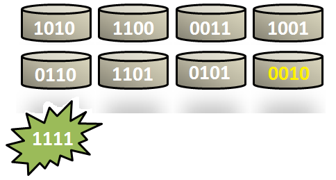
Assume we have the following eight disks and a write should be done at the fifth disk, which should be changed to, say, 1111. (For simplicity we will only look at four bits at each disk, but this could be of any size.)
To get the new parity some actions has to be done. First we read the old data on the blocks that should be changed. We can call this “Disk5-Old” and will be the first IO that must be done. The data that should be written, here 1111, can be called Disk5-New.
Disk5-0ld = 0110
Disk5-New = 1111
We will now use XOR on the old and the new data, to calculate the difference between the old and new. We can call this Disk5-Delta.
Disk5-Delta = Disk5-Old XOR Disk5-New = 0110 XOR 1111 = 1001
When we know the “delta” we will have to commit another read. This is against the old parity. We call this Parity-Old, in this example the old parity is 0010. We will now XOR the old parity with the Disk5-Delta. What is quite interesting is that this will create the new parity, but without the need to read the other six disks.
Parity-New = Parity-Old XOR Disk5-Delta = 0010 XOR 1001 = 1011
When we know the new parity we can write both the new data block and the new parity. This causes two write IOs against the disks and makes up the last of the “penalty”.
So in summary this disk actions that must be done:
1. Read the old data
2. Read the old parity
3. Write the new data
4. Write the new parity
This means that each write against a RAID 5 set causes four IOs against the disks where the first two must be completed before the last two could be performed, which introduces some additional latency.

Thursday, May 12, 2016

cpu vs core vs Socket


https://www.youtube.com/watch?v=Uqv8Y_gkkhc


##[oracle@MISGRP ~]$ lscpu

Architecture:          x86_64
CPU op-mode(s):        32-bit, 64-bit
Byte Order:            Little Endian
CPU(s):                4
On-line CPU(s) list:   0-3
Thread(s) per core:    1
Core(s) per socket:    4

Socket(s):             1  ========> Physical Socket is One

NUMA node(s):          1
Vendor ID:             GenuineIntel
CPU family:            6
Model:                 58
Stepping:              9
CPU MHz:               3200.000
BogoMIPS:              6385.79
Virtualization:        VT-x
L1d cache:             32K
L1i cache:             32K
L2 cache:              256K
L3 cache:              6144K
NUMA node0 CPU(s):     0-3
[oracle@MISGRP ~]$


# cat   /proc/cpuinfo

processor       : 8    =====================> Total Processor is 4 with multithreading

vendor_id       : GenuineIntel
cpu family      : 6
model           : 58
model name      : Intel(R) Core(TM) i5-3470 CPU @ 3.20GHz
stepping        : 9
microcode       : 0x19
cpu MHz         : 3200.000
cache size      : 6144 KB
physical id     : 0
siblings        : 4
core id         : 3

cpu cores       : 4    =======================> 4 cores under 1 Socket

apicid          : 6
initial apicid  : 6
fpu             : yes
fpu_exception   : yes
cpuid level     : 13
wp              : yes
flags           : fpu vme de pse tsc msr pae mce cx8 apic sep mtrr pge mca cmov pat pse36 clflush dts acpi mmx fxsr sse sse2 ss ht tm pbe syscall nx rdtscp lm constant_tsc arch_perfmon pebs bts rep_good nopl xtopology nonstop_tsc aperfmperf eagerfpu pni pclmulqdq dtes64 monitor ds_cpl vmx smx est tm2 ssse3 cx16 xtpr pdcm pcid sse4_1 sse4_2 x2apic popcnt tsc_deadline_timer aes xsave avx f16c rdrand lahf_lm ida arat epb xsaveopt pln pts dtherm tpr_shadow vnmi flexpriority ept vpid fsgsbase smep erms
bogomips        : 6385.79
clflush size    : 64
cache_alignment : 64
address sizes   : 36 bits physical, 48 bits virtual
power management:

----------------------------------------------------------------------------


Saturday, December 5, 2015

RAID 0, RAID 1, RAID 5, RAID 10 Explained with Diagrams


RAID 0, RAID 1, RAID 5, RAID 10 Explained with Diagrams

RAID stands for Redundant Array of Inexpensive (Independent) Disks.
On most situations you will be using one of the following four levels of RAIDs.
  • RAID 0
  • RAID 1
  • RAID 5
  • RAID 10 (also known as RAID 1+0)
This article explains the main difference between these raid levels along with an easy to understand diagram.

In all the diagrams mentioned below:
  • A, B, C, D, E and F – represents blocks
  • p1, p2, and p3 – represents parity

RAID LEVEL 0


Following are the key points to remember for RAID level 0.
  • Minimum 2 disks.
  • Excellent performance ( as blocks are striped ).
  • No redundancy ( no mirror, no parity ).
  • Don’t use this for any critical system.

RAID LEVEL 1

Following are the key points to remember for RAID level 1.
  • Minimum 2 disks.
  • Good performance ( no striping. no parity ).
  • Excellent redundancy ( as blocks are mirrored ).

RAID LEVEL 5


Following are the key points to remember for RAID level 5.
  • Minimum 3 disks.
  • Good performance ( as blocks are striped ).
  • Good redundancy ( distributed parity ).
  • Best cost effective option providing both performance and redundancy. Use this for DB that is heavily read oriented. Write operations will be slow.

RAID LEVEL 10

Following are the key points to remember for RAID level 10.
  • Minimum 4 disks.
  • This is also called as “stripe of mirrors”
  • Excellent redundancy ( as blocks are mirrored )
  • Excellent performance ( as blocks are striped )
  • If you can afford the dollar, this is the BEST option for any mission critical applications (especially databases).

Striping, Mirroring & Parity


Striping, Mirroring & Parity

1. Striping :
For me, Striping is the most confusing RAID level as a beginner and needs a good understanding and explanation. We all know that, RAID is collection of multiple disk’s and in these disk predefined number of contiguously addressable disk blocks are defined which are called as strips and collection of such strips in aligned in multiple disk is called stripe.

RAID Striping

Suppose you have hard disk, which is a collection of multiple addressable block and these blocks are stacked together and called strip and you have multiple such hard disk, which are place parallel or serially. Then such combination of disk is called stripe.
 Note: Without mirroring and parity, Striped RAID cannot protect data but striping may significantly improve I/O performance.


> Disk striping is the process of dividing a body of data into blocks and spreading the data blocks across multiple storage devices, such as hard disks or solid-state drives (SSDs). A stripe consists of the data divided across the set of hard disks or SSDs, and a striped unit, or strip, that refers to the data slice on an individual drive.
2. Mirroring :Mirroring is very simple to understand and one of the most reliable way of data protection. In this technique, you just make a mirror copy of disk which you want to protect and in this way you have two copies of data. In the time of failure, the controller use second disk to serve the data, thus making data availability continuous.
RAID Mirroring

When the failed disk is replaced with a new disk, the controller copies the data from the surviving disk of the mirrored pair. Data is simultaneously recorded on both the disk. Though this type of RAID gives you highest availability of data but it is costly as it requires double amount of disk space and thus increasing the cost.

3. Parity :
As explained above, mirroring involves high cost, so to protect the data new technique is used with striping called parity. This is reliable and low cost solution for data protection. In this method and additional HDD or disk is added to the stripe width to hold parity bit.
Parity is a redundancy check that ensures full protection of data without maintaining a full set of duplicate data.

RAID Parity

The parity bits are used to re-create the data at the time of failure. Parity information can be stored on separate, dedicated HDDs or distributed across all the drives in a RAID set. In the above image, parity is stored on a separate disk.
The first three disks, labeled D, contain the data. The fourth disk, labeled P, stores the parity information, which in this case is the sum of the elements in each row. Now, if one of the Disks (D) fails, the missing value can be calculated by subtracting the sum of the rest of the elements from the parity value.
Hope you have understood the basic of these RAID level. If you have any issue or concern, please let us know through your mails and comment.